Geometry AI Surface Mesher#
Geometry AI Surface Mesher (GAI) combines a geometry processing engine with a surface mesher. It produces mathematically watertight and manifold surface meshes by design, working directly from imperfect or non-watertight CAD without manual geometry repair.
Main characteristics:
produces mathematically watertight and manifold surface meshes by design,
robustly handles non-watertight geometries and patches holes automatically,
handles intersecting solid bodies well,
supports basic spatial transformations and boolean operations on solids (to use these features, define the solids in separate CAD files),
can combine geometries from different sources, including CAD (B-rep) files and discrete surface meshes (STL), into a single watertight surface,
offers the option to set up an analytical wind tunnel farfield, so a farfield body does not need to be present in the input CAD,
can build a half-model from a full-body geometry, or a full-body mesh from a half-body geometry, about the symmetry plane, for more efficient straight-line simulations,
always produces a valid mesh, which makes it well suited to automated, agentic meshing workflows: a first attempt can be generated automatically and then refined only where it matters.
Unlike a standard wrapper, Geometry AI produces a watertight, manifold surface with no intersections or non-manifold elements, directly from the raw CAD input (for a side-by-side illustration, see Comparison with a standard wrapper).
Meshing Process#
The surface mesher performs two main steps:
Geometry Processing
Through the use of Geometry AI, the geometry is processed and prepared for surface meshing. This includes:
applying basic spatial transformations and boolean operations to solids (defined in separate CAD files),
resolving intersections,
patching holes in the geometry,
constructing the farfield geometry,
splitting the geometry to create a half-model.
Surface Meshing
The geometry is meshed using the surface mesher which enables the user to specify all kinds of refinements, also per face of the input geometry.
The behaviour of both steps is driven by a small set of meshing parameters described in the sections below. Each parameter is exposed both in the WebUI (Mesh parameters) and in the Python API (Meshing reference), so the same workflow applies regardless of how the case is set up.
Built for automation
Because Geometry AI always returns a valid, watertight mesh, even from dirty input, it lends itself to automated and agentic workflows. A first mesh can be produced with default parameters, evaluated, and then improved by adding local refinements only where the geometry or the flow requires them, without the manual repair loop that traditional surface meshers need.
Note
The Geometry AI mesher may stop before fully achieving the requested Geometry accuracy if system resource constraints are encountered during surface meshing. When this occurs, a message indicating early termination will appear in the process log, and it reports the finest geometry accuracy that was actually reached. If you observe this, consider increasing the Geometry accuracy value (coarser) globally, or, preferably, apply a finer accuracy only where it is needed with a local geometry refinement (see Local refinements).
Geometry accuracy#
Geometry accuracy is the central parameter of the Geometry AI Surface Mesher, and it is required whenever Geometry AI is enabled. It is the smallest length scale that the geometry processing step resolves accurately: it controls how faithfully the reconstructed surface follows the input CAD, particularly around small features and sharp edges.
A key idea behind Geometry AI is that geometry accuracy is decoupled from the surface mesh resolution. Geometry accuracy governs how well the geometry itself is captured, while the surface mesh density is controlled separately (see Controlling the surface mesh). A smaller value therefore resolves finer geometric detail at the cost of longer geometry processing; it is not a direct mesh-density control. It can still raise the node count indirectly and locally, because finer detail (for example sharper edges and higher local curvature) needs more nodes to represent, but for a smooth shape the effect on the overall count is small.
Geometry accuracy is an absolute length: it corresponds to the smallest edge you want to capture. It does not scale with the overall size of the model, so the same trailing edge needs the same geometry accuracy whether it sits on a small or a large body.
Resolution carries a cost: the finer the geometry accuracy, the longer the geometry processing and meshing take. Lowering the global value to capture one small local feature refines the whole model and inflates both the mesh node count and the meshing time. The recommended workflow is therefore:
Start from the default global Geometry accuracy. It is set automatically when Geometry AI is enabled and is a sensible baseline for the bulk of the geometry.
Add local geometry refinements on the specific faces that carry small features (thin trailing edges, small gaps, tight radii), to set a finer local accuracy only there (see Local refinements).
This keeps the global geometry accuracy, and the meshing time, moderate while still resolving the small features that matter.
The mesher accepts a wide range of values. The main guard is a sanity floor: if the value is finer than 1e-5 times the bounding box diagonal, the mesher warns that it is unreasonably fine for the model and recommends increasing it.
Note
In the WebUI, Geometry accuracy and the mesh input lengths (such as Surface max edge length, Sealing size, and Minimum passage size) use the project length unit by default, but you can also enter an explicit unit. Make sure the unit is correct: a value given in the wrong length unit (for example one far smaller than intended) can produce a much finer mesh than expected and lead to very long meshing times. In the Python API each value carries its own explicit unit.
Cleaning up the geometry#
Since Geometry AI reconstructs a watertight surface from the input, it exposes several controls for cleaning up imperfect or overly detailed CAD before meshing. All of the options below are specific to the Geometry AI Surface Mesher.
Sealing size: closes physical gaps and holes in the geometry that are smaller than this threshold (for example the central hole of a torus, or a deliberate slot you do not want the mesh to pass through). These physical openings do not usually prevent a watertight surface, so this parameter is mainly about user intent: it decides which real openings should be sealed shut. It can be set to zero to disable this sealing. Even at zero, Geometry AI still closes the non-physical gaps (small cracks and leaks between faces) that would otherwise break watertightness, because producing a watertight surface does not depend on this parameter.
Preserve thin geometry: controls how aggressively thin features (for example trailing edges, fins, or thin walls) are retained. With this option off, thin features need a thickness of roughly three times the Geometry accuracy to survive; with it on, thin features down to a scale of the Geometry accuracy are preserved accurately, at the cost of a finer local mesh.
Remove hidden geometry: removes internal geometry that is not visible to the flow (for example components sealed inside a closed body). The companion Minimum passage size sets the smallest opening through which an internal region is still considered connected to the exterior; internal regions reachable only through passages smaller than this are treated as hidden. If not specified, it is derived from Geometry accuracy and Sealing size.
Remove baffle faces: when hidden geometry removal is active, faces that are exposed to the exterior on both sides (baffles, zero-thickness walls) are removed. Turning this option off instead thickens such faces into a closed shell so they are retained.
Best practice
Reach for these cleanup options before resorting to manual CAD repair. Sealing size and Remove hidden geometry are usually enough to turn a dirty, non-watertight production model into a meshable one, which is the main reason to choose this mesher for automotive and other detailed geometries.
Controlling the surface mesh#
Once the geometry is processed, the surface mesh density is governed by the following parameters:
Curvature resolution angle: the maximum angular deviation allowed between a surface element and the underlying surface. Lower values capture curvature more accurately but increase the node count.
Surface max edge length: an upper bound on surface cell edge length. It is enforced regardless of the other surface controls, so it acts as a hard cap on element size. Because the surface mesh nodes are always projected onto the geometry, a small Surface max edge length also yields good curvature resolution on its own (a fine edge length cannot leave a curved surface under-resolved). The recommended practice is to keep a generous (large) global value and tighten it only where needed through a local surface refinement (see Local refinements).
Surface max aspect ratio: the maximum aspect ratio of surface cells. Lower values force more isotropic cells.
Surface edge growth rate: the rate at which surface edges grow in length away from regions of high curvature or small max edge length constraints. Typical values are
1.1to1.25.Resolve face boundaries: when enabled, the boundaries between adjacent faces are resolved accurately with anisotropic refinement. Enable this when face-to-face boundaries (for example between a body and an appendage) must be captured sharply.
Target surface node count: when set, the mesher scales the curvature metric so that the surface mesh reaches approximately this number of nodes, then enforces Surface max edge length on top of the result. This is a quick way to control overall mesh density without tuning individual length scales. The target is approximate: it is not a guaranteed minimum or maximum. Internally the value is converted to a target mesh complexity and the curvature metric is rescaled uniformly to match it, so the realised node count can land somewhat above or below the requested number. Two consequences follow from this:
The actual node count is higher than the target whenever Surface max edge length is the binding constraint. If you request a low target node count together with a fine Surface max edge length, the edge length dominates, the node count overshoots the target, and the curvature scaling has limited influence.
It does not change the geometry-resolving behaviour, which remains governed by Geometry accuracy.
To let the target node count drive the mesh, keep Surface max edge length generous so it does not bind.
Running a mesh refinement study#
To study mesh convergence, scale the whole surface mesh up or down consistently rather than changing one parameter in isolation. The recommended approach uses Target surface node count as the single driver:
Multiply Target surface node count by a refinement factor
x(for example2for a finer level,0.5for a coarser one).Scale Surface max edge length by
1 / sqrt(x)at the same time. Node density on a surface scales with the inverse square of the edge length, so this keeps the edge-length cap consistent with the requested node count and prevents it from binding unexpectedly between levels.
Keeping the two in step means the curvature scaling continues to drive the mesh at every level, so successive meshes differ by a controlled, roughly uniform factor. If Surface max edge length is left fixed while only the node count changes, it will eventually become the binding constraint and the meshes will stop refining as expected (see Target surface node count above).
Local refinements#
Most tuning of a Geometry AI mesh should be done locally, on the specific faces that need it, rather than by changing global values. Two per-face refinement types are available:
A geometry refinement overrides Geometry accuracy (and, optionally, Preserve thin geometry, Sealing size, and Minimum passage size) on a selected set of faces. This is the recommended way to resolve a small or detailed feature without refining the whole model.
A surface refinement overrides surface mesh controls such as Surface max edge length, Curvature resolution angle, and Resolve face boundaries on selected faces.
Both are documented for the WebUI under Geometry refinement and Surface refinement, and in the Python API under the Meshing reference (GeometryRefinement and SurfaceRefinement).
Note
With the Geometry AI surface mesher a uniform refinement (a volumetric refinement region) also refines the surface mesh inside the region. See Effect on the surface mesh for how each workflow treats this.
Farfield and half-model setup#
Geometry AI can build the farfield analytically as part of geometry processing, so a separate farfield body is not required in the input CAD. Two farfield styles are available:
An automated farfield generates a (semi)sphere or cylinder sized relative to the geometry bounding box. This is the general-purpose choice for external aerodynamics.
A wind tunnel farfield builds a rectangular tunnel and is intended for ground-vehicle and wind-tunnel-correlation work. It supports several floor treatments (static floor, fully moving floor, central belt, and wheel belts) to represent moving-ground conditions.
For symmetric configurations, the mesher can split the geometry into a half-model about the symmetry plane, which roughly halves the mesh size and is well suited to straight-line (zero-yaw) simulations. The half-model option requires the Geometry AI Surface Mesher together with the beta volume mesher.
These options are configured in the WebUI under Farfield and in the Python API under the Farfield zone specifications.
Best practices#
Start from the default global Geometry accuracy. It is a sensible baseline for the bulk of the geometry; refine locally from there rather than lowering it everywhere, which costs meshing time across the whole model.
Refine locally, not globally. Use geometry refinements on the few faces that need fine resolution rather than lowering the global value for the whole model.
Use the cleanup options instead of manual CAD repair. Sealing size and Remove hidden geometry handle most dirty, non-watertight production geometries.
Enable Preserve thin geometry only where needed. It is most useful applied through a local geometry refinement on thin parts (trailing edges, fins), keeping the rest of the mesh coarse.
Watch the process log for early termination. If meshing stops before reaching the requested accuracy, the log reports the finest accuracy achieved; coarsen the global value or move the fine accuracy into a local refinement.
Keep Surface max edge length generous globally. Use a large global value so it does not silently dominate, and tighten it locally with a surface refinement only where finer elements are needed.
Drive overall density with Target surface node count. It is the simplest single lever for controlling mesh size; for a refinement study scale it by
xand Surface max edge length by1 / sqrt(x)together (see Running a mesh refinement study).Use a half-model for symmetric, zero-yaw cases to roughly halve the mesh size.
For general meshing guidance that applies across all workflows, see the meshing knowledge base.
Working with sharp edges and thin features#
Geometry AI represents sharp edges implicitly through the reconstructed surface rather than conforming mesh edges to feature lines, so edge-based refinements do not apply: surface edge refinement (SurfaceEdgeRefinement) is not supported with the Geometry AI mesher. To sharpen the representation of an edge, refine the Geometry accuracy (a smaller value), locally where possible. Likewise, features thinner than the active thickness threshold (see Preserve thin geometry above) are best resolved with a local geometry refinement or by enabling Preserve thin geometry on those parts.
For geometries whose accuracy hinges on conforming the mesh to sharp feature edges, the Surface Mesher (watertight input) or the Snappy Surface Mesher can be a good complement.
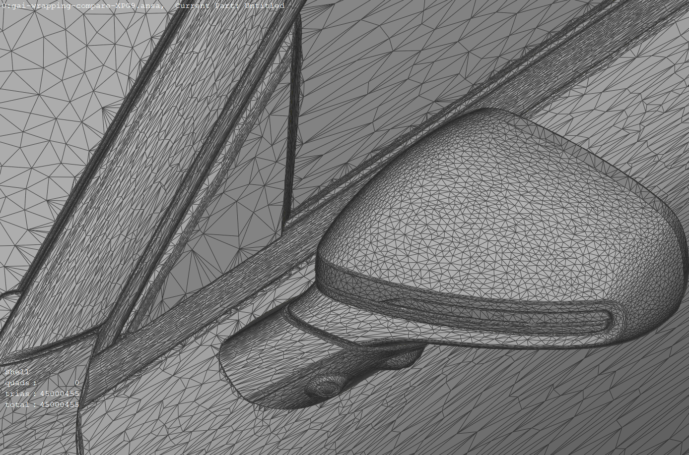
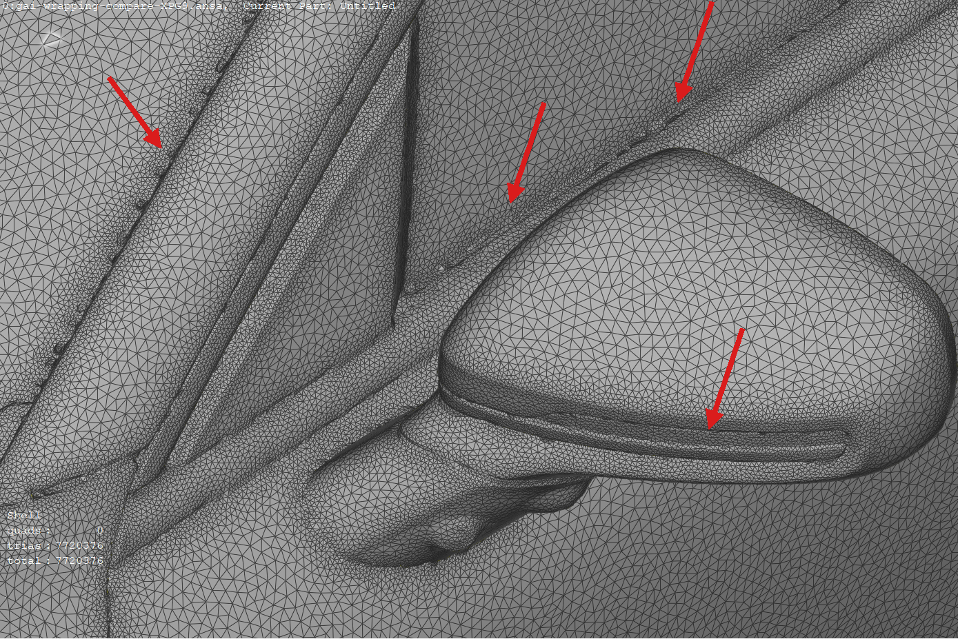
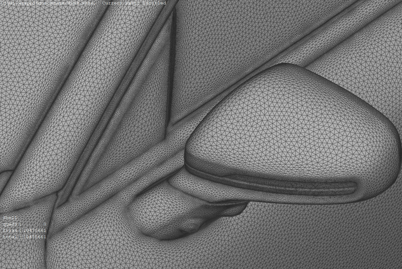
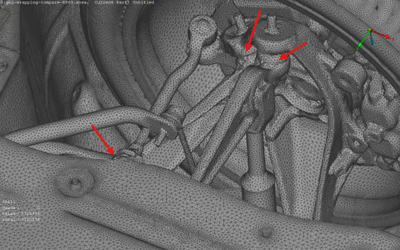
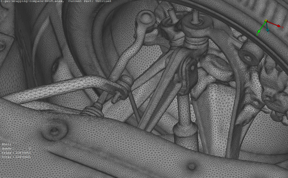
Comparison with a standard wrapper#
The comparisons below show the input geometry, the result of a standard wrapper, and the Geometry AI surface for the same detailed regions. The red arrows highlight regions where the standard wrapper produces defects (intersections or non-manifold elements) that Geometry AI avoids.
Input geometry |
Standard wrapper |
Geometry AI |
|---|---|---|
|
|
|
Input geometry |
Standard wrapper |
Geometry AI |
|---|---|---|
|
|
|
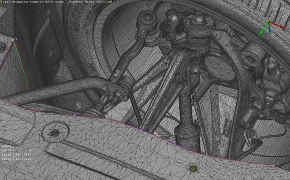
Examples#
Examples of meshing using Geometry AI can be found in the Python API Example Library. Specifically look at:
Recommended for:
non-watertight geometries,
faulty low quality geometries,
intersecting solid bodies,
geometries of automotive production vehicles.
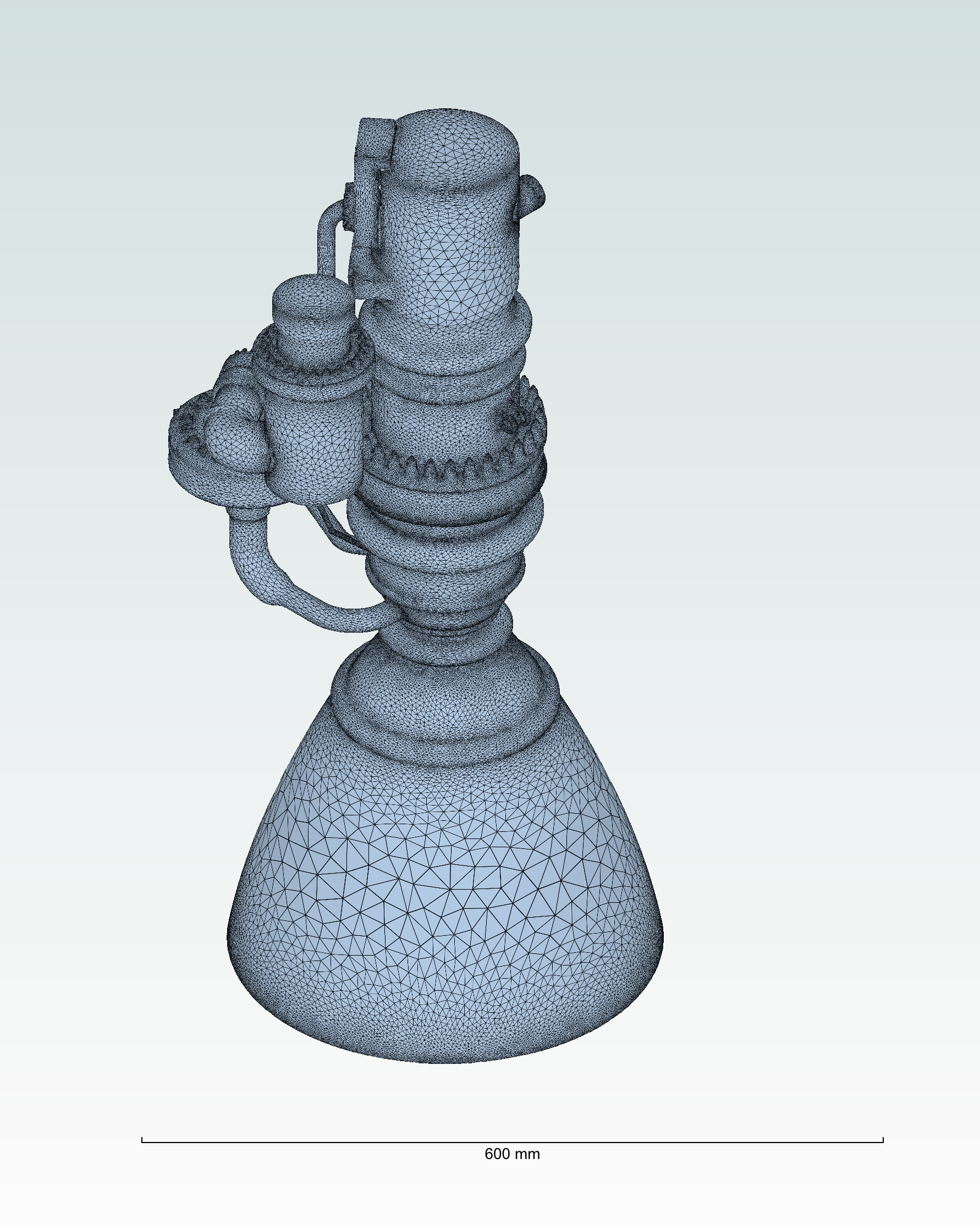
Example of a mesh generated using the Geometry AI Surface Mesher.#