STEP Format CAD Import for Automated Meshing#
Rather than building the geometry in ESP, the user can load a STEP file into the Engineering Sketch Pad (ESP), label the faces and edges in ESP, and save the labeled geometry as an EGADS file. Then, the EGADS file can be directly uploaded to our cluster via the Python API or using the Web UI.
Quick Example#
Here is an example CSM script for importing the example.step file and labeling the faces.
import $/example.step -1
group -1
store $prism
store $cylinder
store $box
mark
   restore $prism
      attribute faceName $prism
      attribute groupName $prism
   restore $cylinder
      attribute faceName $cylinder
      attribute groupName $cylinder
   restore $box
      attribute faceName $box
      attribute groupName $box
dump $/example.egads 0 1 0
For
importanddump, the$/means the STEP and EGADS files are in the same folder as the CSM file.For
import, the-1means import all solid bodies.For
group, the-1means ungroup the solid bodies so the user canstorethem separately later on. The user can determine the order of the ungrouped solid bodies interactively in ESP.For
dump, the0 1 0meansremove=false toMark=true withTess=falsei.e. all solid bodies frommarkwill be exported into the EGADS file. More details aboutdumpcan be found in the ESP documentation.

Fig. 7.2.7 Three solid bodies imported from a STEP file and labeled in ESP.#
As shown in the example above, immediately after the user restores a solid body, the user can assign attributes to the solid body as well as all faces belonging to this solid body. For more options on selecting and attributing faces and edges, see Adding Face and Group Attributes and Adding Edge Attribute
Currently face attributes from third-party CAD software will not be passed to our automated meshing workflow, though we are currently developing a feature to extract ADVANCED_FACE names from STEP files, which will pass the face attributes through our workflow.
Common Issues#
This section summarizes common issues when using a STEP file as an entry point for automated meshing.
Lofting Surfaces#
When lofting the surfaces, it is strongly recommended to avoid sharp corners between edges or small gaps between adjacent surfaces.

Fig. 7.2.8 Example of a sharp corner and a small gap.#
The schematic above shows two typical issues: (a) the sharp corner between surface-A/B/C could cause surface mesh failure on surface-B (b) the gap between surface-C/D can result in a surface mesh mismatch. It is worth noting that the size of the gap between surface-C/D is exaggerated for illustration. As shown in the screenshot below, in reality, the gap could be so small that it is almost invisible to the human eye.
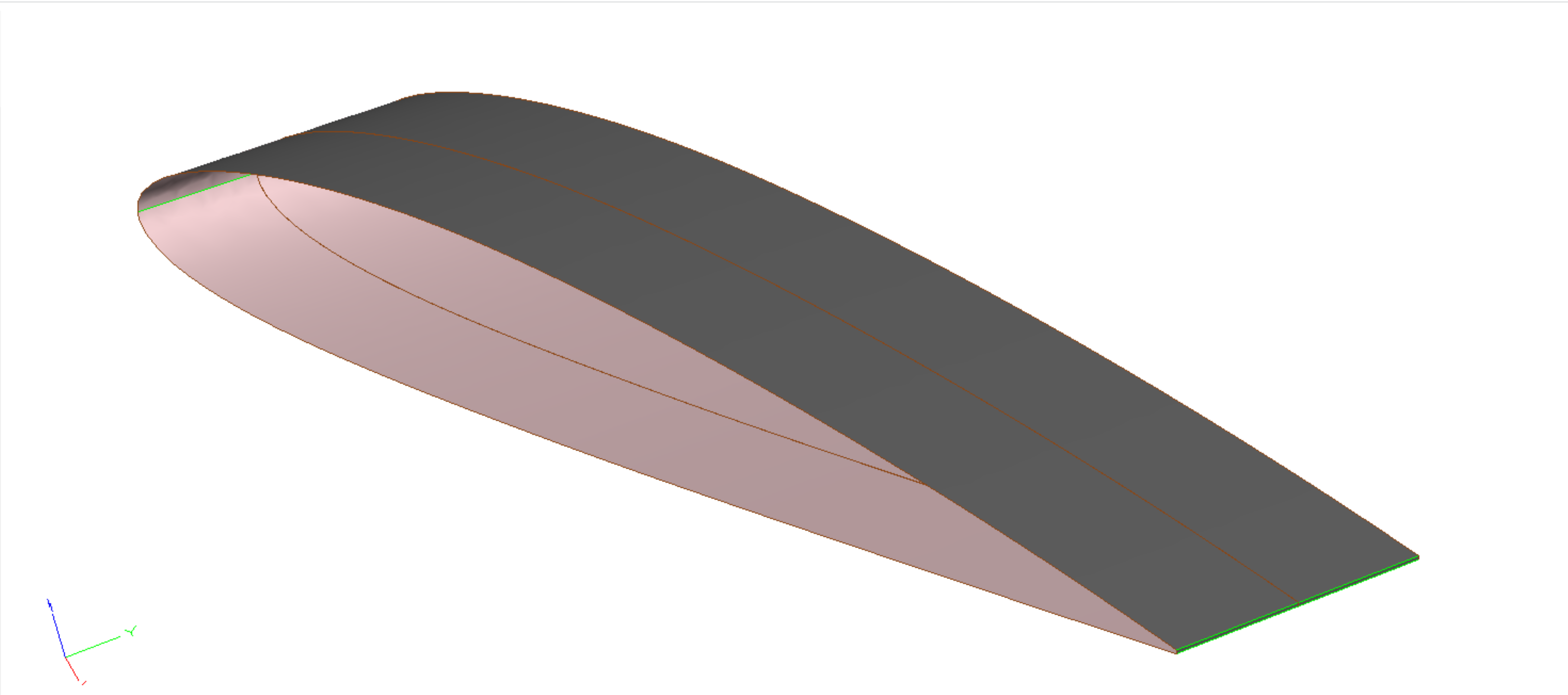
Fig. 7.2.9 Small/invisible gap on a sheet body in ESP.#
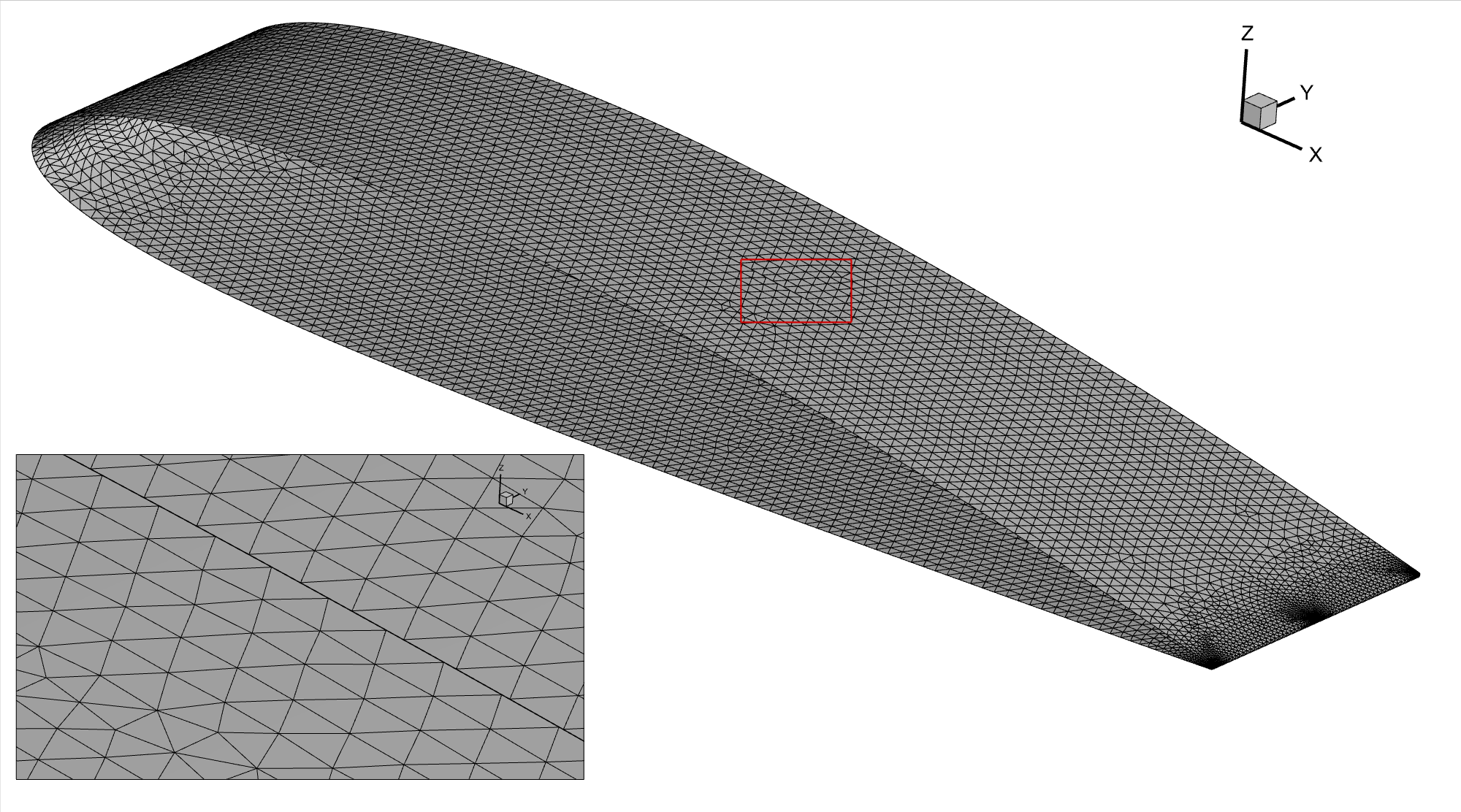
Fig. 7.2.10 Surface mesh mismatch due to the small/invisible gap.#
Boolean Operations#
When improving a design, changes often affect only a small portion of the geometry, leaving the rest unaltered. In such cases, users can import a baseline STEP file and then create a parametric geometry in ESP to represent the modified part. Before performing the UNION operation, it is critical to ensure that the additional parametric geometry is fully extruded into the baseline geometry. This precaution prevents the occurrence of small gaps or sharp corners in 3D space.

Fig. 7.2.11 Left: Good example. The root cross-section of the pylon is completely inside the wing. Right: Bad example, there is a sharp corner/small gap at the junction between pylon and wing, which could cause volume mesh failure.#
Solid Body v.s. Sheet Body#
Solid bodies output to STEP files are more robust than sheet bodies.
In ESP, when dealing with sheet bodies, patching gaps/holes and “sewing” patches into a closed solid body is possible. However, this process heavily depends on the tolerance and may lead to issues during surface mesh generation. Hence, direct export of solid bodies to STEP files is strongly recommended.
During surface mesh generation, we will always check the watertightness. Gaps or holes will trigger warning messages as follows: "WARNING! There is only one neighboring face for an edge." As aforementioned, these gaps may be extremely small and invisible to the human eye.
As shown in the following screenshots, when preparing a half or quasi-3D model, it is recommended to keep the side faces on the “symmetric plane” and create solid bodies. The automated mesher will handle the side faces, eliminating the need for manual removal of these side faces by the user.

Fig. 7.2.12 Left: Good example. Solid body, side faces are kept. Right: Bad example. Sheet body, the user does not need to create holes on the “symmetric plane”#