6.6. Automated Meshing for Internal Flow#
This tutorial shows how to create a mesh for internal flow using the automated meshing process.
Geometry#
As shown in Fig. 6.6.1, the geometry is a wind tunnel enclosing a sphere that is supported by four cylindrical struts. The corresponding CSM file is provided, so the readers can easily reconstruct the geometry on their local machines.
Several details are worth emphasizing in the CSM file:
For internal flow, a single solid body representing the fluid must be provided to the automated meshing process. To do this, once the wind tunnel (box) and the sphere with struts are constructed, the next step is to
subtractthe sphere and struts from the wind tunnel.Fig. 6.6.1 shows the
faceNameandgroupNameattributes on the faces of the wind tunnel. In general faces with the samefaceNamewill be treated as the same surface patch for assigning surface (maxEdgeLength) and volume (firstLayerThickness) mesh attributes. Conversely, the user can set different surface and volume mesh attributes for faces with a differentfaceName. Faces with the samegroupNamewill be considered as the same boundary when exporting the CGNS file.

Fig. 6.6.1 Sphere in wind tunnel, geometry with face attributes. sideNegY is hidden to show the interior of the wind tunnel.#
Meshing#
The meshing parameters is set up as follows:
 1 geometry.group_faces_by_tag("faceName")
 2 farfield = fl.UserDefinedFarfield(name="farfield")
 3 params = fl.SimulationParams(
 4     meshing=fl.MeshingParams(
 5         defaults=fl.MeshingDefaults(
 6             surface_max_edge_length=1.2 * fl.u.m,
 7             curvature_resolution_angle=15 * fl.u.deg,
 8             surface_edge_growth_rate=1.2,
 9             boundary_layer_first_layer_thickness=1e-6,
10             boundary_layer_growth_rate=1.2,
11         ),
12         refinement_factor=1.0,
13         volume_zones=[farfield],
14         refinements=[
15             fl.SurfaceRefinement(
16                 name="sphere", max_edge_length=0.1, faces=[geometry["sphere"]]
17             ),
18             fl.SurfaceRefinement(name="strut", max_edge_length=0.01, faces=[geometry["strut"]]),
19             fl.BoundaryLayer(
20                 name="floor", first_layer_thickness=1e-5, faces=[geometry["floor"]]
21             ),
22             fl.PassiveSpacing(
23                 name="adjacent2floor", type="projected", faces=[geometry["adjacent2floor"]]
24             ),
25             fl.PassiveSpacing(name="ceiling", type="unchanged", faces=[geometry["ceiling"]]),
26         ],
27     ),
28 )
UserDefinedFarfieldis used to generate the farfield volume zone based on the supplied geometry.MeshingDefaultsdefines the global settings for surface and volume meshing. For example,surface_max_edge_lengthgoverns the mesh size on all faces.Regarding the details
refinementssetting, please note that:When setting up parameters for the specific faces, the
faceNametag defined in the CSM file can be used to select a group of faces:The grouping tag MUST be chosen first (
geometry.group_faces_by_tag("faceName")) to allow the usage of group selection.All the keys of
geometry(e.g."floor"ingeometry["floor"]) need to match the resulting grouped face names underfaceNametag in the CSM file.
To overwrite the global
surface_max_edge_lengthsetting, we define localSurfaceRefinement.max_edge_lengthfor the sphere and strut faces.For the
floorfaces, we setBoundaryLayer.first_layer_thicknessas 1e-5 to overwrite the global value of 1e-6. The first layer thicknesses provided here are just for illustration. The users need to adjust these values according to the target \(y^+\) in their simulations.For the
ceilingfaces,PassiveSpacing.typeis set asunchanged, hence the anisotropic layers won’t be grown from the ceiling. Meanwhile, the surface mesh on the ceiling remains unaltered when generating the volume mesh.For the faces adjacent to the floor
adjacent2floor,PassiveSpacing.typeis set asprojected. The surface mesh on those faces is updated when populating the volume mesh. As shown in Fig. 6.6.2, the “spacing” of anisotropic layers grown from the floor are “projected” onto the faces adjacent to the floor.
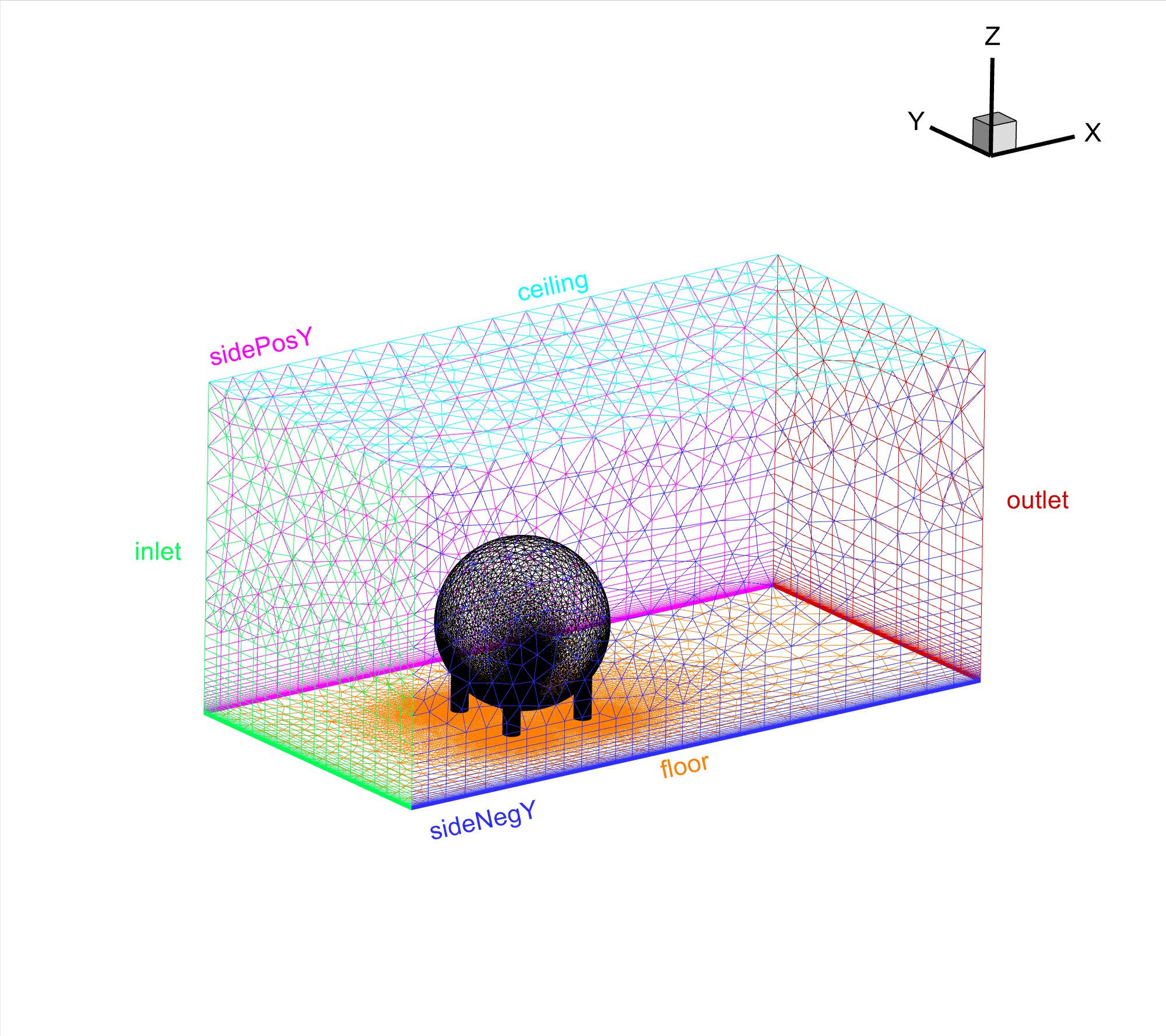
Fig. 6.6.2 Sphere in wind tunnel, populated volume mesh.#