3.1. Automated Meshing#
Overview#
Flow360 offers automated meshing, from a CAD geometry to a surface mesh and finally to a volume mesh. The supported CAD formats are CSM and EGADS. The output volume meshes are in CGNS format.
Meshing settings#
Mesh in flow360 can be defined using settings, which fall into one of the three categories visible below:
Setting |
Default |
Description |
|---|---|---|
REQUIRED |
Default/global settings for meshing. |
|
REQUIRED |
Creation of new volume_zones. Can be of type |
|
OPTIONAL |
Additional fine-tunning for the mesh on top of default settings. |
More details about each of those categories can be found here:
Surface Meshing#
The surface mesher takes the geometry file and user defined settings as inputs to generate a surface mesh. Here, settings can be defined either in WebUI or through Python API, and are used to control the surface mesh resolution. Example of defining surface meshing settings in Python API:
import flow360 as fl
with fl.SI_unit_system:
    params = fl.SimulationParams(
        meshing=fl.MeshingParams(
            defaults=fl.MeshingDefaults(
                surface_max_edge_length=1,
                surface_edge_growth_rate=1.2,
                curvature_resolution_angle=12 * fl.u.deg
            )
        ),
        ...
    )
The surface mesh can be created by submitting the project with a geometry file and providing previously set up SimulationParams containing MeshingParams via the Python API:
import flow360 as fl
project = fl.Project.from_file("path/to/geometry.csm", "MyProject")
project.generate_surface_mesh(params, "MySurfaceMesh")
print(project.surface_mesh.id)
- Inputs
WebUI project that contains an uploaded geometry
params:
SimulationParams
- Outputs
surface mesh on cluster
return the
surface_mesh.id
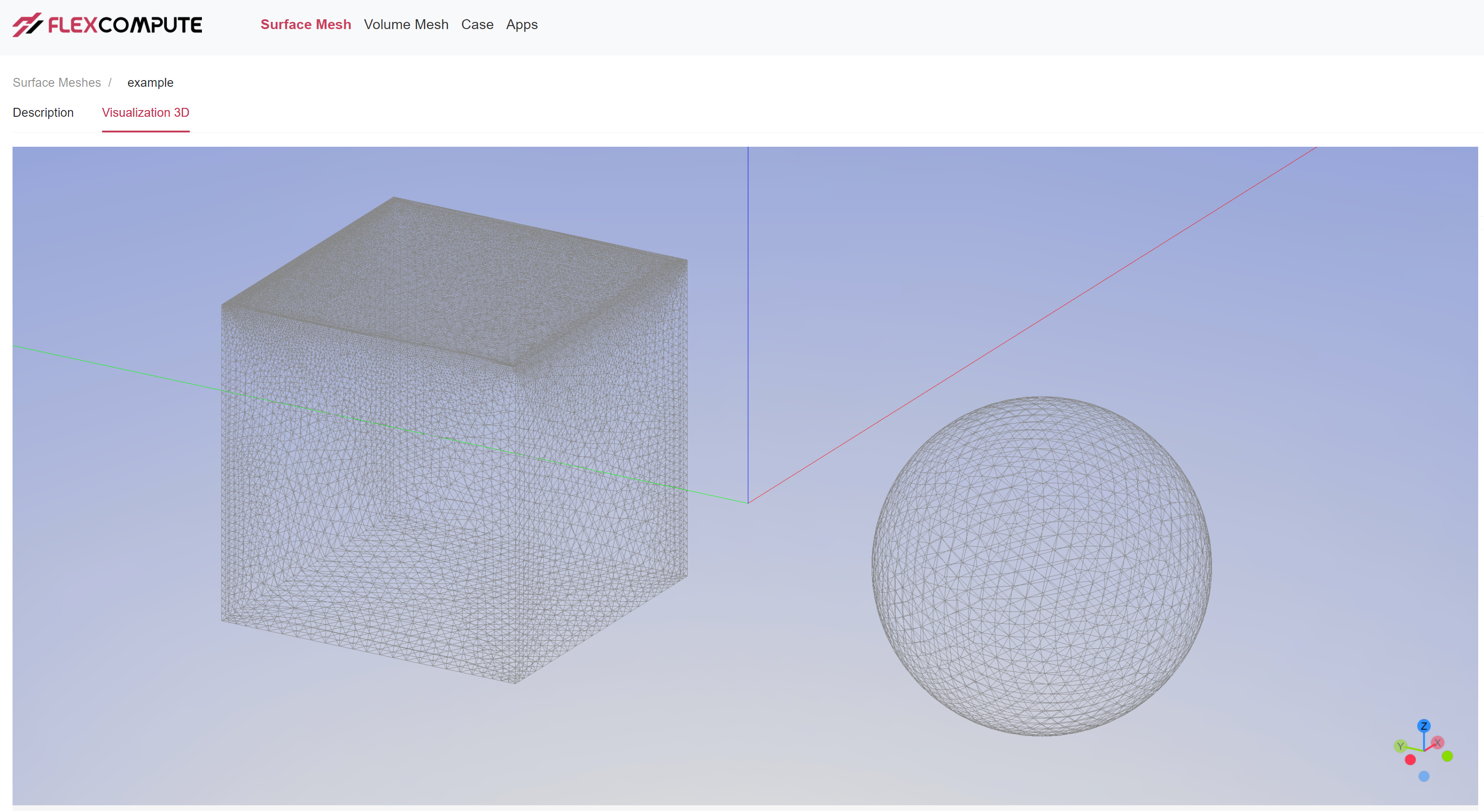
Fig. 3.1.1 Auto-generated surface mesh. An extra refinement is applied to the top face of the box.#
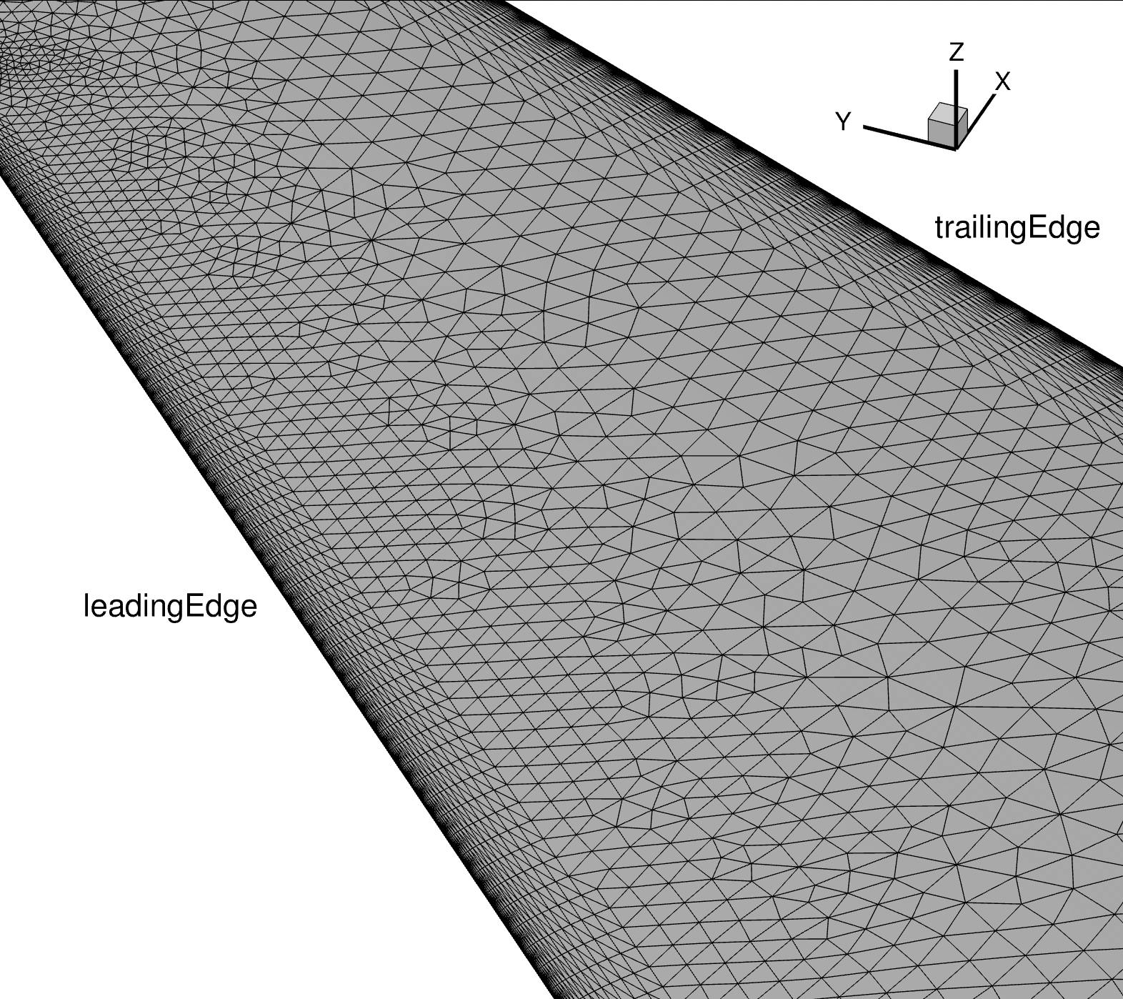
Fig. 3.1.2 Surface mesh on a wing. Anisotropic layers are growing from leading and trailing edges.#
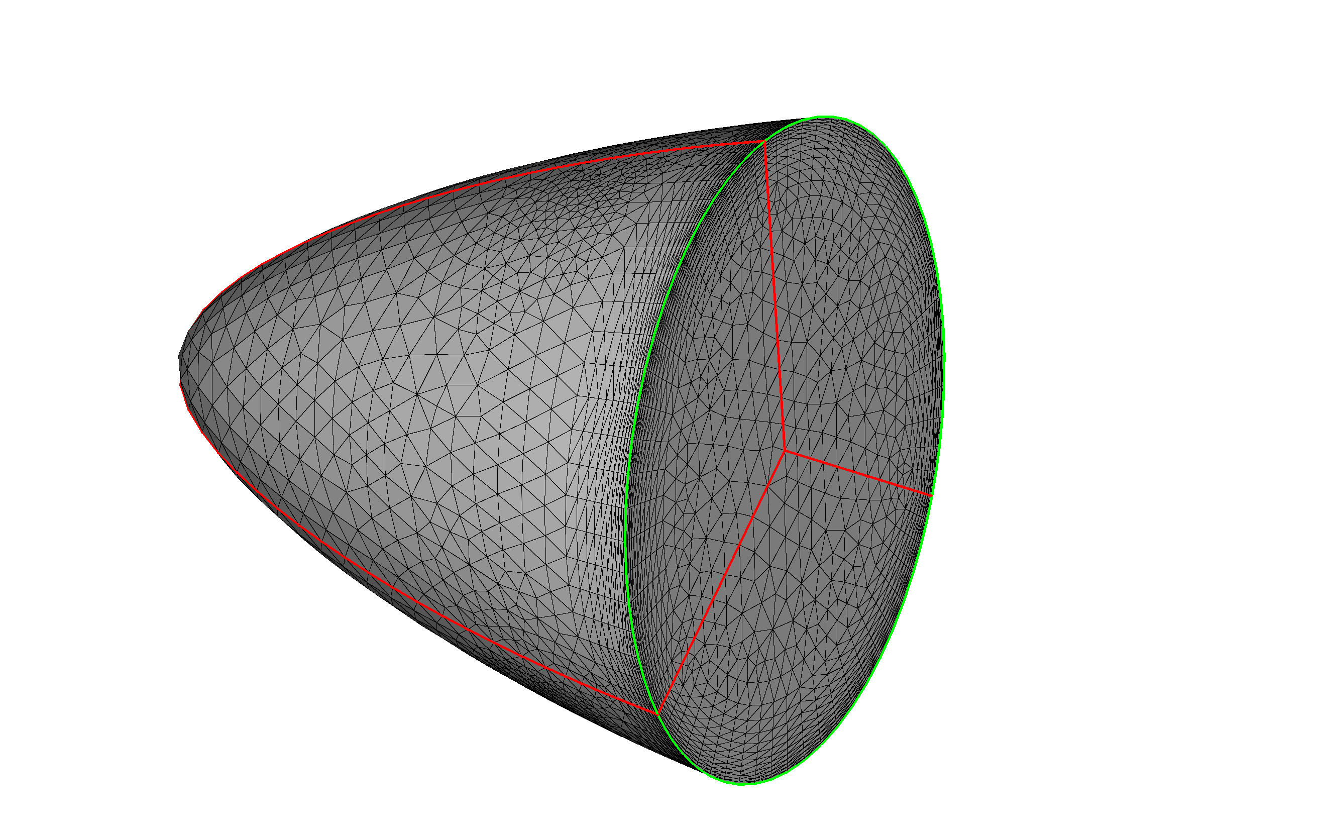
Fig. 3.1.3 Surface mesh on a hub. Anisotropic layers are growing from hubCircle (green). The anisotropic spacing on the neighboring patches is “projected” to hubSplitEdge (red) and updates the nodes distribution along hubSplitEdge.#
Volume Meshing#
The volume mesher takes a surface mesh and user defined settings to generate a volume mesh. These settings are defined either through WebUI or Python API and determine the volume mesh resolution.
They contain boundary_layer_first_layer_thickness and boundary_layer_growth_rate of 3D anisotropic layers, the size/location/resolution of refinements and etc.
Below is an example of defining volume meshing settings in Python API:
import flow360 as fl
with fl.SI_unit_system:
    cylinder1 = fl.Cylinder(name="Cylinder1", axis=(0, 1, 0), center=(1, 0.2, 0), outer_radius=3, height=2)
    farfield = fl.AutomatedFarfield(name="farfield", method="auto")
    params = fl.SimulationParams(
        meshing=fl.MeshingParams(
            defaults=fl.MeshingDefaults(
                boundary_layer_growth_rate=1.15,
                boundary_layer_first_layer_thickness=3e-6,
            ),
            refinement_factor=1.25,
            gap_treatment_strength=0.7,
            volume_zones=[farfield],
            refinements=[
                fl.UniformRefinement(name="refinement1", spacing=0.2, entities=[cylinder1])
            ]
        ),
        ...
    )
In the above Python script, there is a cylindrical volume mesh refinement zone centered at (1, 0.2, 0). This refinement will have a uniform spacing of 0.2 m in this volume zone. The volume mesh can be created from an existing surface mesh and parameters for the volume meshing, for example, using the Python API:
import flow360 as fl
project = fl.Project.from_file("path/to/geometry.csm", "MyProject")
project.generate_volume_mesh(params, "MyVolumeMesh")
print(project.volume_mesh.id)
- Inputs
WebUI project that contains an uploaded geometry
params:
SimulationParams
- Outputs
volume mesh on cluster (in CGNS format)
Flow360Mesh.json on cluster
return the
volume_mesh.id

Fig. 3.1.4 Left: WebUI showing the refinement zone. Right: auto-generated volume mesh.#

Fig. 3.1.5 Auto-generated volume mesh. Left: sliced at y=1. Right: sliced at y=-1.#
defaults#
This section describes the default settings for both surface and volume meshing.
Option |
Default |
Type |
Description |
|---|---|---|---|
1.2 |
SURFACE |
[float] Growth rate of the anisotropic layers grown from the edges. |
|
REQUIRED |
SURFACE |
[float] Default maximum edge length for surface cells. This can be overridden with |
|
12 |
SURFACE |
[float] Default maximum angular deviation in degrees. This value will restrict:
1. The angle between a cell’s normal and its underlying surface normal.
2. The angle between a line segment’s normal and its underlying curve normal.
This can not be overridden per face.
|
|
1.2 |
VOLUME |
[float] Default growth rate for volume prism layers. This can not be overridden per face. |
|
REQUIRED |
VOLUME |
[float] Default first layer thickness for volumetric anisotropic layers. This can be overridden with |
|
1 |
VOLUME (ADVANCED) |
Adjusts all spacings in refinement regions and first layer thickness to generate r-times finer mesh, where r i s the |
|
0 |
VOLUME (ADVANCED) |
Narrow gap treatment strength used when two surfaces are in close proximity.
Takes a value between 0 and 1, where 0 is no treatment and 1 is the most conservative treatment.
This parameter has a global impact where the anisotropic transition into the isotropic mesh.
Its impact on regions without close proximity is negligible.
|
Example of defining MeshingDefaults in Python API:
import flow360 as fl
with fl.SI_unit_system:
    params = fl.SimulationParams(
        meshing=fl.MeshingParams(
            defaults=fl.MeshingDefaults(
                surface_max_edge_length=1,
                surface_edge_growth_rate=1.2,
                curvature_resolution_angle=12 * fl.u.deg,
                boundary_layer_growth_rate=1.1,
                boundary_layer_first_layer_thickness=1e-5
            ),
            refinement_factor=1.1,
            gap_treatment_strength=0.2
        )
        ...
    )
Gap treatment examples:

Fig. 3.1.6 Different gap_treatment_strength strength. The larger gap_treatment_strength is, the more space is dedicated to isotropic mesh than anisotropic mesh in narrow gaps.#
volume_zones#
Settings used for defining AutomatedFarfield and RotationCylinder volume zones.
Volume zone |
Default |
Description |
|---|---|---|
REQUIRED |
Automatically created farfield volume zone. |
|
OPTIONAL |
Rotation cylinder volume zone. |
Example of defining volume_zones in Python API:
import flow360 as fl
with fl.SI_unit_system:
    farfield = fl.AutomatedFarfield(name="Farfield", method="auto")
    cylinder = fl.Cylinder(name="Cylinder", axis=[0, 1, 0], center=[1, 1, 1], outer_radius=10, height=3)
    rotation_cylinder = fl.RotationCylinder(
        name="RotationCylinder",
        spacing_axial=0.5,
        spacing_circumferential=0.3,
        spacing_radial=1.5,
        entities=cylinder
    )
    params = fl.SimulationParams(
        meshing=fl.MeshingParams(
            ...
            volume_zones=[farfield, rotation_cylinder]
        ),
        ...
    )
AutomatedFarfield#
Settings for automatic farfield volume zone generation.
Option |
Default |
Description |
|---|---|---|
Farfield |
Name of the |
|
auto |
By default, the farfield shape will be automatically determined by the volume mesher. The user can prescribe the farfield shape if needed.
|
RotationCylinder#
The mesh on
RotationCylinderis guaranteed to be concentric.The
RotationCylinderis designed to enclose other objects, but it can’t intersect with other objects.Users could create a donut-shape
RotationCylinderand put their stationary centerbody in the middle.This type of volume zone can be used to generate volume zone compatible with
Rotationmodel.
Option |
Default |
Description |
|---|---|---|
Rotation cylinder |
Name of the |
|
REQUIRED |
[float] Spacing along the axial direction. |
|
REQUIRED |
[float] Spacing along the radial direction. |
|
REQUIRED |
[float] Spacing along the circumferential direction. |
|
REQUIRED |
List of volumes where |
|
|
OPTIONAL |
List of entities enclosed by |
refinements#
Describes the settings used for defining additional settings for refining the mesh on top of MeshingDefaults.
Refinement |
Default |
Description |
|---|---|---|
OPTIONAL |
Setting for growing anisotropic layers orthogonal to the specified |
|
OPTIONAL |
Setting for refining surface elements for given |
|
OPTIONAL |
Setting for growing anisotropic layers orthogonal to the specified |
|
OPTIONAL |
Setting for controling the mesh spacing either through adjacent |
|
OPTIONAL |
Setting for uniform spacing refinement inside specified region of mesh. |
|
OPTIONAL |
Setting for axisymmetric refinement inside specified region of mesh. |
Example of defining refinements in Python API:
import flow360 as fl
with fl.SI_unit_system:
    farfield = fl.AutomatedFarfield(name="Farfield", method="auto")
    cylinder = fl.Cylinder(name="Cylinder", axis=[0, 1, 0], center=[1, 1, 1], outer_radius=10, height=3)
    rotation_cylinder = fl.RotationCylinder(
        name="RotationCylinder",
        spacing_axial=0.5,
        spacing_circumferential=0.3,
        spacing_radial=1.5,
        entities=cylinder
    )
    params = fl.SimulationParams(
        meshing=fl.MeshingParams(
            ...
            volume_zones=[farfield, rotation_cylinder]
        ),
        ...
    )
SurfaceEdgeRefinement#
Setting for growing anisotropic layers orthogonal to the specified Edge (s).
Option |
Default |
Description |
|---|---|---|
SurfaceEdgeRefinement |
Name of the |
|
REQUIRED |
Method for determining the spacing. Can be one of:
|
|
|
REQUIRED |
List of |
SurfaceRefinement#
Setting for refining surface elements for given Surface.
Option |
Default |
Description |
|---|---|---|
SurfaceRefinement |
Name of the |
|
REQUIRED |
[float] Maximum edge length of surface cells. |
|
|
REQUIRED |
List of |
BoundaryLayer#
Setting for growing anisotropic layers orthogonal to the specified Surface (s).
Option |
Default |
Description |
|---|---|---|
BoundaryLayerRefinement |
Name of the |
|
REQUIRED |
[float] First layer thickness for volumetric anisotropic layers grown from given |
|
|
REQUIRED |
List of |
PassiveSpacing#
Passively control the mesh spacing either through the adjacent Surface’s meshing settings or doing nothing to change existing surface mesh at all.
Option |
Default |
Description |
|---|---|---|
PassiveSpacingRefinement |
Name of the |
|
REQUIRED |
[str] Type of the
|
|
|
REQUIRED |
List of |
UniformRefinement#
Uniform spacing refinement inside specified region of mesh.
Option |
Default |
Description |
|---|---|---|
UniformRefinement |
Name of the |
|
REQUIRED |
The required refinement spacing. |
|
REQUIRED |
List of |
AxisymmetricRefinement#
The mesh inside the
AxisymmetricRefinementis semi-structured.The
AxisymmetricRefinementcannot enclose/intersect with other objects.Users could create a donut-shaped
AxisymmetricRefinementand place their hub/centerbody in the middle.AxisymmetricRefinementcan be used for resolving the strong flow gradient along the axial direction for actuator or BET disks.The spacings along the axial, radial and circumferential directions can be adjusted independently.
Option |
Default |
Description |
|---|---|---|
AxisymmetricRefinement |
Name of the |
|
REQUIRED |
[float] Spacing along the axial direction. |
|
REQUIRED |
[float] Spacing along the radial direction. |
|
REQUIRED |
[float] Spacing along the circumferential direction. |
|
REQUIRED |
List of |