After having uploaded a CAD geometry into our new project (see this Quick Start tutorial) we now need to mesh it. We will do so using our automated meshing toolchain.
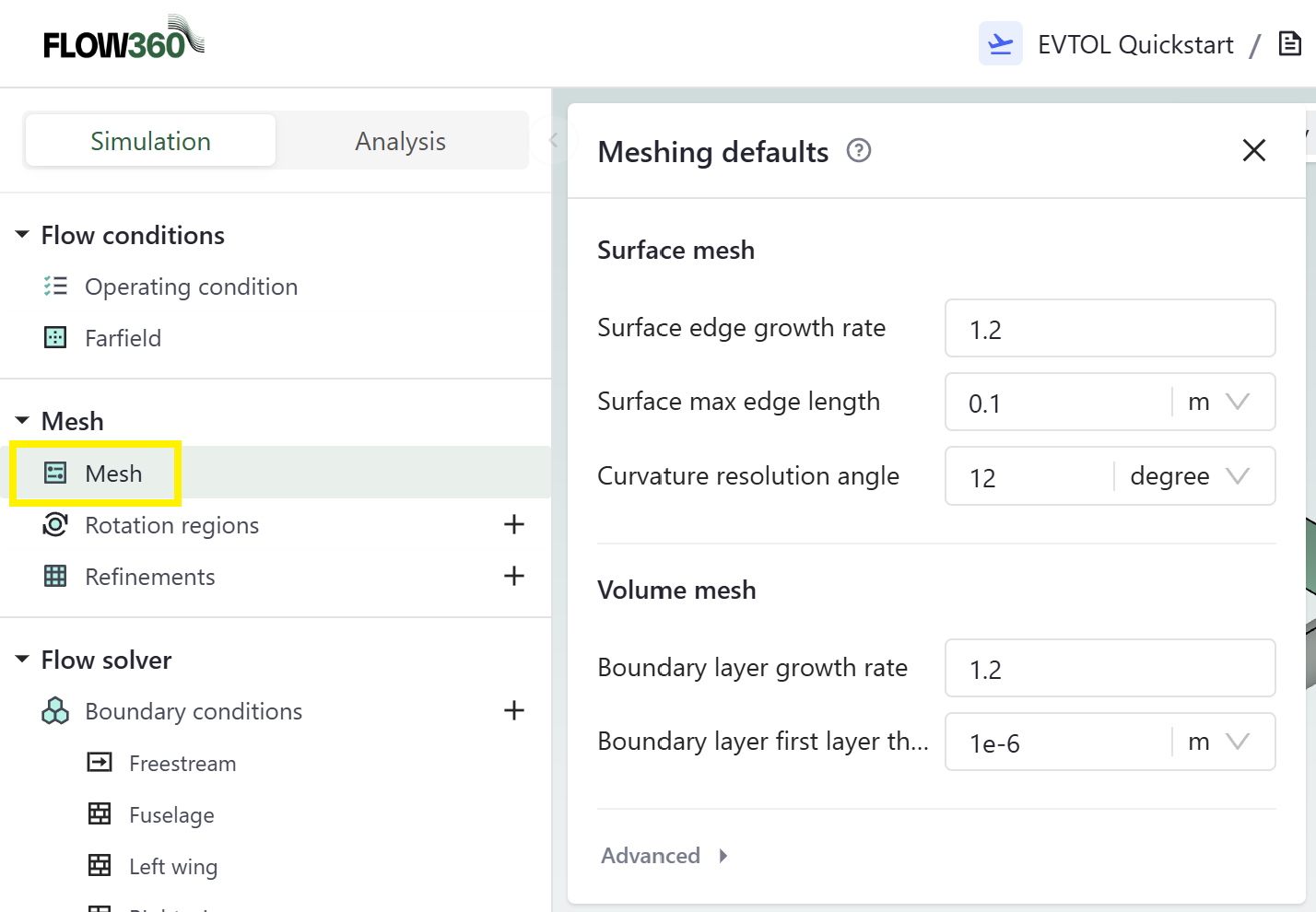
When opening the project that we created in the previous Quick Start tutorial you will notice a Mesh tab on the top left. When clicking on that Mesh tab, a pop up window will appear with the meshing default parameters where you can change them as required to create both a surface mesh and then a volume mesh.
Most values are filled in by default using overall dimensions from the CAD you have uploaded. However, you are expected to fill in the Surface max edge length and Boundary layer first layer thickness values. Please enter 0.1 m as a Surface max edge length and 1e-6 m as a Boundary layer first layer thickness.
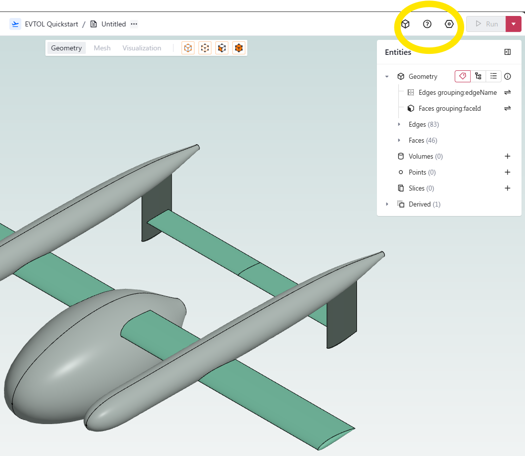
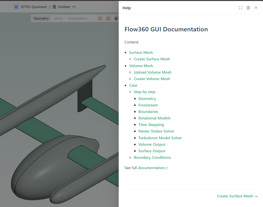
If you are unsure about what values to enter for each of those meshing parameters please look at our meshing guidelines. You can also learn more about what each parameter does by opening our help (?) window and looking into the Surface mesh and Volume mesh sections.
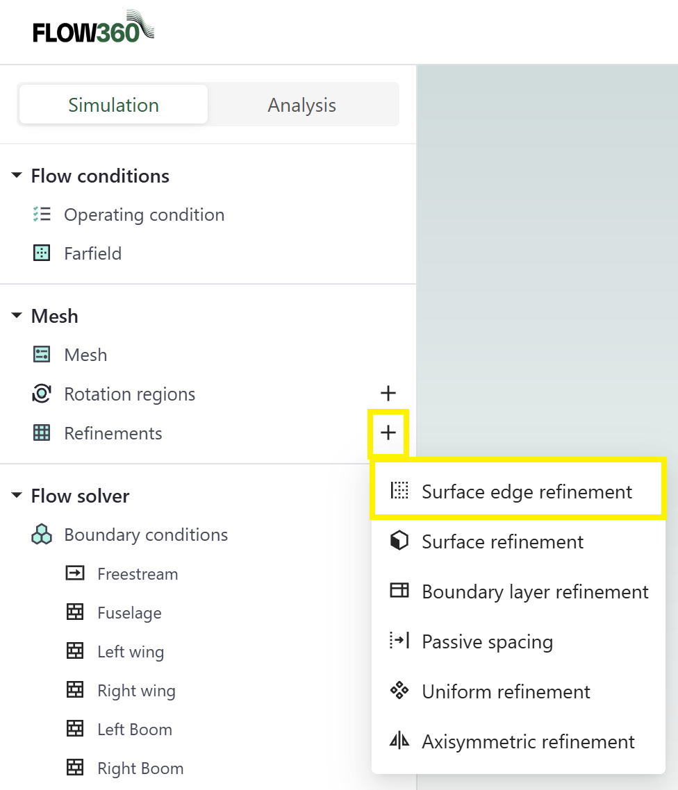
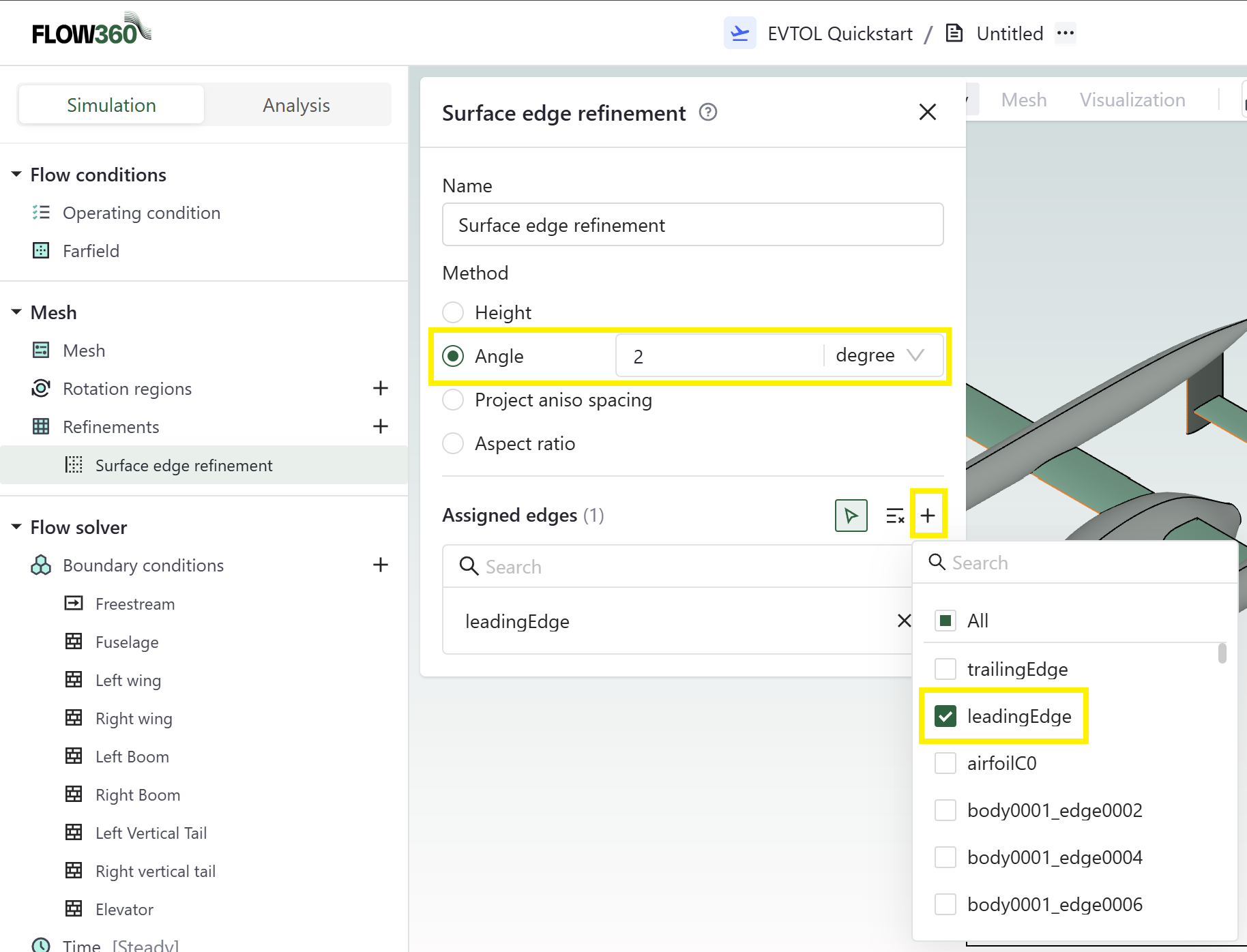
We will also need to specify some leading edge refinements criterion to properly capture the geometry curvature in those regions. Please follow the steps outlined below to specify the leading edge surface mesh criterion of angle 2°. As in, force the mesh to refine until it captures all CAD curvature within 2°.
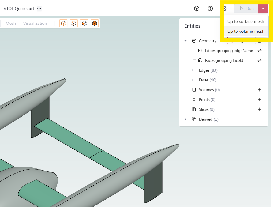
Now that required settings have been defined, you can launch the meshing tool chain. If you look at the Run icon at top right and click on the downwards facing triangle you will notice that you have the option of creating just the surface mesh or both the surface mesh then the volume mesh.
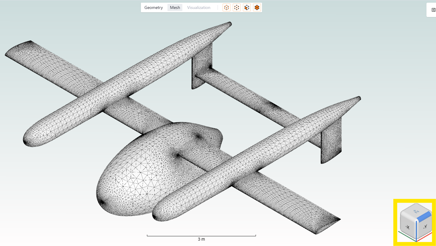
After a few seconds, you will notice that the surface mesh is completed and the resulting surface mesh will be displayed. It is easy to visually inspect the resulting surface mesh.
To pan the view left and right, press the right mouse button.
Zooming in and out can be done by the mouse scroll wheel.
To rotate the geometry, simply left mouse click on a point on the geometry, keep the mouse button pressed and move the mouse around. The point you have clicked on becomes the rotation point.
A very useful feature is the View cube on the bottom right of the screen. Clicking on any faces or bevel will bring the associated view.